|
Dynamic Testing of A/D Converters Using Sinusoid Signals
Theoretical Background
Dynamic parameters of an analog-digital converter, such as
signal-to-noise ratio or total harmonic distortion, are important in the
characterization or comparison of such converters. Some of these parameters
can be found using time-domain methods. Among these methods, curve fitting is
widely used in testing. During the measurement, a high-quality sinusoid signal
is applied to the input of the device under test (DUT). The output samples are
saved into a y (y[n]) vector. A sinewave is fitted to the
measurement results, which consists of a series of numbers. This fit is
basically an estimate of the unknown input signal. Calculating the difference
between the measured values and the fitted sinewave, some consequences may be
drawn about the dynamic parameters of the converter. Based on this difference
(the so-called residual vector), the rms value of the error can be calculated,
and from that the effective number of bits (ENOB) in the converter and the
signal-to-noise and distortion ratio (SINAD) can be determined.
Let us assume that the input signal applied to the input of the converter is
given in the form

where A, fi, Φ and C
are the amplitude, the frequency, the phase and the constant offset of the
signal, respectively. Let's take M samples from this signal, at
fs sampling rate. A sinewave signal should be fitted to the
column vector y[n], n=1..M containing the output samples. There
are two different cases: the frequency of the input signal is known or unknown.
In the first case there are three parameters to determine (A, Φ,
C), while in the second, four (A, Φ, C,
fi). Let us assume that the frequency is known, thus, discuss
only the three-parameters fitting in the following. (Note that from the
theoretical and research viewpoint the four-parameters fitting is much more
interesting - see the publications related to this topic.)
The fit with the least squares error can be found by minimizing
the following cost function
where  , the parameter-vector containing the unknown variables is
p=[Acos(Φ), -Asin(Φ), C]T.
Creating the following matrix , the parameter-vector containing the unknown variables is
p=[Acos(Φ), -Asin(Φ), C]T.
Creating the following matrix
the cost function given in (2) can be formulated as  . At the minimum
value of the cost function the parameter-vector becomes: . At the minimum
value of the cost function the parameter-vector becomes:

Note that if the sampling is coherent, i.e., the number of
periods of the incoming signal is integer, then the solution of the
parameter-vector can be found in closed form:
which (ignoring the sign of the second equation) is equal
to the calculation of the real and imaginary components of the discrete
Fourier-transform formula at a given input frequency and the real component at
DC.
By using the estimated parameter-vector, the estimators of the
amplitude, phase and offset can be easily calculated ( , ,  if if  and and  if if  , and finally , and finally  ), thus the
estimated input signal can also be calculated ( ), thus the
estimated input signal can also be calculated ( ). Subtracting this
signal from the measured samples, the error vector (the residual) can be
calculated. ). Subtracting this
signal from the measured samples, the error vector (the residual) can be
calculated.
The SIgnal-to-Noise-And-Distortion ratio (SINAD) is defined as
the ratio of the input signal's power and the power of the residual vector,
containing the noise and the harmonics:
where

i.e., the variance of the residual vector (the difference
between the vector of the fitted sinewave and the vector of the measured
samples). Since the SINAD parameter compares the noise power to the incoming
signal's power, it is important to drive the input of the converter
rail-to-rail, but not to overdrive.
Knowing the error, the effective number of bits can be also
calculated, where the rms value of the measured error is compared to that of the
ideal quantization noise:

where N is the number of bits of the converter, and
Q is the nominal code-width of the converter.
Figure 1 shows the steps described above in the case of an
ideal quantizer (MATLAB simulation). The original sinewave is quantized, then a
sinewave is fitted to the quantized samples, then the residual vector is
calculated by subtracting the fitted sinewave and the input signal. In this
ideal case the residual vector contains only the quantization error.
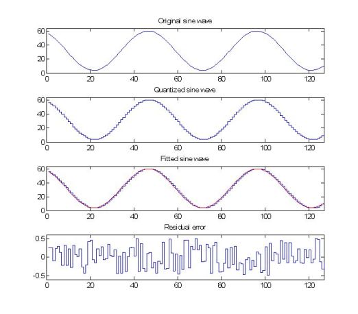
Fig. 1. The steps of sine fitting
Results
During the first part of the research, a MATLAB-implementation
of the sinewave-fit routines defined in the standard IEEE-STD-1241 has been
released. The program can be downloaded from the URL http://www.mit.bme.hu/projects/adctest/.
Figure 2 shows the input and the result window of the program.
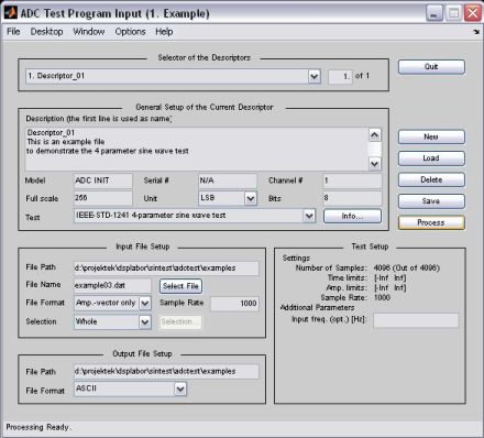
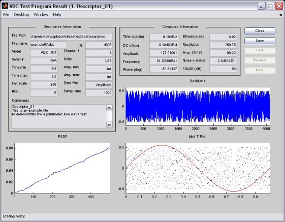
Fig. 2. The input and the result windows of the ADC test
program
Among the theoretical results, the parameters of the sine wave
fit algorithm, which were not exactly specified in the standard have been
defined (e.g., exact stop condition of the iteration as a function of the number
of bits of the converter). Another current research direction is the study of
non-ideal effects. (One topic: how big the error caused by the fact that the
quantization error of a sine wave is not gaussian. In this case the
least-squares fit is not the best estimator. Another topic: how big the error
caused by the fact that the histogram of the sinewave is not uniform, i.e., at
the top and the bottom the converter's errors are weighted. What can be done to
minimize this error, etc.)
Related Publications:
|
T. Z. Bilau, T. Megyeri, A. Sárhegyi, J. Márkus,
and I. Kollár, "Four-parameter fitting of sine wave testing results:
Iteration and convergence," Computer Standards and
Interfaces, vol. 26, no. 1, pp. 51-56, Jan. 2004. |
Suggestions to improve the four-parameter fitting: determination of the
starting frequency by means of interpolated FFT; derivation of the
achievable precision of the estimated input frequency as a function of the
number of bits in the converter (parametric derivation and theoretical
limits). |
|
J. Márkus and I. Kollár, ADC
Test Data Evaluation Program for MATLAB, Budapest
University of Technology and Economics, Department of Measurement and
Information Systems, 2006. |
Program to demonstrate the three- and four-parameter sine wave fitting
algorithms. In addition to the IEEE-STD-1241, different iteration
paramereters can be set in the program: stop condition, starting value
calculation method, etc. |
Further publications on A/D converters can be downloaded from here.
Useful links:
Further information: János Márkus
|