Nowadays cheap and easy-to-use solutions are commercially
available to build up complex distributed systems. In these systems, autonomous
nodes can communicate and cooperate with each other over a shared communication
channel; usually over a wireless medium. Based on this technology, amazing
concepts like wireless sensor networks (WSN) or Internet of Things (IoT) have
already become reality. Besides the first applications involving low sampling
rate data acquisition (e.g., environmental monitoring), powerful systems enable
the direct real-time interaction between the nodes. Hence distributed signal
processing can also be performed. Recently some control systems take the
advantage of flexible and scalable communication.
However, the design of a
distributed signal processing system is challenging, due to the inherent
unreliability of networked communication. The problem is particularly difficult
if a control system with real-time feedback is to be designed, as the stability
of a networked closed-loop system is not obvious. Moreover, in several cases the
resources of the nodes are also limited in order to ensure cost-effective and
power-aware operation.
In the following sections these basic issues of distributed
systems will be introduced.
Most of the results presented hereinafter are
general, but primarily we focus on the cases where adaptive algorithms (some LMS
based algorithms, or the so-called resonator based algorithms) are implemented
in the system.
The architecture of a distributed signal processing system
is depicted in Fig. 1. Besides the structure is flexible enough to represent a
wide range of distributed systems, it contains all of the important components
required for signal processing.
Fig. 1. Block diagram of the system.
A sensor network is attached to a multiple-input
multiple-output (MIMO) physical system, and the individual sensors transmit raw
or preprocessed measurement data to a central processing unit over a shared
communication network. The central unit aggregates the sensors’ data, and
generates control signals which are directly connected to the physical MIMO
plant. The system model in Fig. 1 clearly shows that signal sensing and
processing are performed in a distributed manner by the sensor network and a
central controller.
In order to be able to achieve practical experiences and to
test the theoretical results, a test system was also developed. The test
application selected for the realization using wireless sensors was active noise
control (ANC). The architecture of the test system and an experimental
arrangement can be seen in Fig. 2 and Fig. 3, respectively.
Fig. 2. Architecture of the test system (testbed).
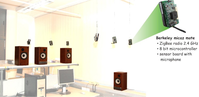
Fig. 3. An experimental arrangement (sensors and
loudspeakers).
The choice of ANC as test application was motivated by the
knowledge-base obtained in this field in our laboratory, and it is also
reasonable from scientific and practical aspects due to the following facts:
-
ANC systems are real MIMO systems, the acoustic cross-coupling
is formed inherently.
-
The acoustic plant is present everywhere, it is easy to
install and reconfigure (changing the transfer functions).
-
Sensors and actuators (microphones and loudspeakers) are cheap
and easily available.
-
Real-time feedback is essential.
-
The bandwidth of acoustic signal is a real challenge for a
sensor network but not impossible.
-
Not safety-critical: instability doesn't result in dangerous
situation or the damage of the system.
In the test system 8 bit microcontrollers with
2.4 GHz ZigBee radio were deployed as sensors, and the central controller
was realized with a 32 bit floating point DSP. The sampling frequency was
set to 1.8 kHz.
Synchronization
In traditional centralized signal processing systems,
sampling and signal processing are performed on the same device. However, in
distributed systems, where the sampling and the signal processing are performed
on different devices, the signal is distorted in a sense, which is to be
compensated.
Perhaps the most unpleasant effect caused by the distributed
signal sensing is the uncertain amount of delay in the data transmission. Since
a constant delay can easily be compensated, system designers generally aim to
use deterministic protocols for data transmission in order to ensure constant
delay. However, the delay caused by the unsynchronized nodes has also serious
effect, since it is not known in advance, so its compensation is not possible.
The uncertainty of the delay in the feedback can lead even to the instability of
the system.
In order to solve the problem of synchronization we have
proposed a PLL-like synchronization mechanism as shown in Fig. 4. This mechanism
aligns the sampling instants of the different sensor nodes such that the time
difference between them remains almost constant, so it can be taken into account
during the system design.
Fig. 4. Synchronization mechanism.
The effect of unsynchronized operation on the stability of a
system is illustrated in Fig. 5, where a resonator-based ANC system was
operated with wireless sensors. It is also shown that the synchronization
mechanism presented above holds the delay in the feedback loop constant, so it
ensures the stability of the system.

Fig. 5. Measurement example for the illustration of the
effect of synchronization on the stability (left column: synchronization is
inactive, right column: synchronization is active; top: noise signal after ANC
has been turned on, bottom: time delay variation).
It can be seen that the delay Td can be
held on a constant level if the synchronization is switched on permanently
(bottom right figure), but if the synchronization is switched off, this delay
changes continuously (bottom left figure). In our system the excess delay caused
by the unsynchronized operation is bounded by one sampling period interval,
since the central controller always processes the most recent sample. The time
functions on the top show the error signal (remaining noise) after the ANC
system has been turned on. One can see that the ANC system works properly if the
synchronization is active (top right time function: the error signal is
decreased and remains on a constant level), but if the synchronization is
inactive, the excess delay Td changes continuously and if it
reaches a critical value indicated with red shaded area, the system becomes
unstable, i.e., the error signal increases. The critical delay can be calculated
using the stability condition of resonator-based ANC systems.
Bandwidth Limit
In real-time systems, a hard time limit is specified for
the transmission time for all of the data collected by the sensors, so the
bandwidth limit of the communication channel can be the bottleneck of the whole
system. Taking a realistic example, if a 2.4 GHz ZigBee network with 250
kbps bandwidth is used, and an acoustic signal of a bandwidth of 1-2 kHz should
be transmitted in real-time, only 3-4 sensors can be deployed in the network
taking also into account the communication overhead.
The bandwidth of a
communication link is highly determined by standards, costs and the power
consumption, so the bandwidth constraints are often resolved by using the
computational capacity of the sensor nodes. Intelligent sensors are able to
achieve data reduction by preprocessing the signal. Since sensor nodes often
have limited computational resources, only a simple method can be used for data
compression. In order to alleviate the limitations posed by the bandwidth
constraints of communication channel, two solutions are proposed, both of them
are based on the local preprocessing of the signal on the sensor nodes:
Sign-error algorithms
The basic block diagram of a system implementing a
sign-error algorithm is shown in Fig. 6.
Fig. 6. Block diagram of the sign-error
algorithms.
The operation principle is very simple, so it can be
implemented on sensors with limited resources. The sensor measures the error
signal, and performs a one bit truncation, i.e., it forwards only the signum
function of the error signal. Since the sign of the error signal can be
represented on one bit (it is positive or negative), it means reasonable signal
compression. The advantage of the algorithm is its simplicity, and its
disadvantage is that the performance is deteriorated: since only the sign of the
error signal is known, the parameters of the control signal are tuned with
constant steps. The step size of the algorithm should be set as low as possible
in order to achieve low steady-state error, but low step size results in slow
convergence, hence a trade-off is required.
The algorithm can be further
improved if the sensor measures the absolute mean value of the error signal for
periods of length L samples, and transmits this mean value to the central
controller. This is a trade-off between the two extrema when the amplitude of
the error signal is known in every time instant or it is not known at all.
A
measurement result can be seen in Fig. 7, where a periodic noise is
suppressed using the resonator-based noise control algorithm. As one can
conclude, approximately the same steady-state noise suppression is achieved, but
the convergence time of the simple sign error algorithm is higher than that of
the other two algorithms. However, the performance (noise suppression and
convergence speed) of the improved sing-error algorithm is close to the original
algorithm, and its communication bandwidth demand is reduced to the half of the
original bandwidth.
Fig. 7. Measurement results for the sign-error
algorithms.
Distributed resonator-based algorithms
The block diagram of the distributed resonator-based algorithm
can be seen in Fig. 8, and its operation principle is as follows. The
sensor nodes measure the disturbance signal, and each node implements locally a
Fourier-analyzer (FA). Each node transmits the Fourier-coefficients
to the central controller through a gateway, and the central controller uses
these coefficients for the tuning of the control signal.
The synchronization
should also be solved in this system as well. On the one hand, the synchronous
sampling on the sensors should be solved on the sensor nodes using the PLL-like
synchronization method shown in Fig. 4, on the other hand the sensors
should periodically update the signal frequency and the reference value of the
phase of the complex exponential basis function that are used for the
Fourier-decomposition.
The advantage of the algorithm is that the
Fourier-coefficients can be transmitted to the central controller less
frequently than the signal samples, since the Fourier-coefficients change slower
than the signal itself. The disadvantage of the algorithm is that it poses
severe requirements on the sensor nodes since the Fourier-decomposition should
be performed in real time, which is not a simple task on an 8 bit
microcontroller. Furthermore, the number of Fourier-coefficients that can be
transmitted is limited for two reasons: the limited computational capacity of
the sensor nodes and the bandwidth limit of the communication channel.
Theoretically, such a system is able to integrate infinite number of sensors.
Practical limitations stem from the slow changes of Fourier coefficients and the
computational capacity of the central controller.
Fig. 8. Block diagram of the distributed resonator-based
algorithms.
Fig. 9 shows a measurement for comparing the original and
the distributed resonator based ANC algorithms. As the measurement shows, the
steady-state and the transient performance of the distributed resonator-based
algorithm is close to that of the original resonator-based algorithm.

Fig. 9. Measurement result for the distributed
resonator-based algorithm.
Data loss
Data loss cannot be avoided in real-time communication
systems due to the time limit of data transmission and the inherently unreliable
physical layer. Data loss can be especially dangerous in closed-loop systems,
since if one or more samples of the feedback signals are lost, then the control
loop becomes temporarily opened. The first straightforward question which
emerges is whether the system remains stable depending on the data loss
pattern.
In our model the stability of the closed-loop system can easily be
ensured, since the plant itself should be stable if adaptive algorithms like LMS
or resonator-based structure is used. However, the quality of the convergence is
highly influenced by the data loss pattern. Our aim is to find definite
conditions for the convergence of the adaptive algorithm. Convergence means that
the state variables of the algorithm tend to their optimal values, where the
optimal solution is the limit of the variables without data loss.
In order to
model the data loss, a so-called data availability indicator function, Kn, is
introduced: Kn = 1 if the sample is processed, and
Kn = 0 if the sample is lost at time index
n. Furthermore let N denote the number of resonators (i.e.,
the number of Fourier-coefficients used to represent the signal). Fig. 10
also shows how data loss can be taken into account in the signal path: data loss
can be modeled as a controlled switch which is closed if a sample is available,
and it is open if the sample is unavailable.
Fig. 10. Modeling the data loss in the resonator-based
structure.
Our goal regarding the issue of analyzing the effect of
data loss on resonator-based algorithms was to find such conditions which enable
us to predict whether the state variables of the resonator-based algorithms
converge to their optimal values or not. The conditions can be evaluated using
the pattern of data loss and the parameters of the algorithm. Since the theory
and nomenclature related to the analysis of data loss is extensive, we don’t
give here a comprehensive overview of the topic but highlight the most important
results, and interested readers are referenced to the pblications at the bottom
of this page.
The practically important case, when the data loss doesn't
allow the proper convergence of the algorithm is when samples are missing every
time from the same position(s) within the periods of the signal transmitted by
the sensors. In other words, this is the case when the data loss pattern
Kn is correlated with the signal.
Fortunately, one can
find also such conditions under which the convergence can exactly be ensured.
One of the practically most important conditions is the following: if the data
loss ratio is less than a critical value, then the state variables of the
resonator-based adaptive controller converge to their optimal values. Data loss
ratio can be defined in several ways, but loosely speaking it is the ratio of
the number of processed samples to the total number of samples. Some important
extensions and corollaries of this condition are found in (e.g., random data
loss described by Bernoulli- or Markov-process doesn't hinder the convergence).
As rule of thumb, the critical value of data loss ratio can be approximated
by the reciprocal of the number of resonators. For example, if the disturbing
signal contains 5 harmonic components, i.e., there are N = 2*5 + 1 = 9
resonators, and the data loss ratio is less than 1/9 = 11.1%, the convergence of
the control algorithm can be strongly suspected even without exactly evaluating
the conditions.
In order to illustrate the effect of data loss, two
simulation examples are shown in Fig. 11. The sampling frequency is
10 kHz, and a periodic disturbing signal with the frequency of 50 Hz
is assumed (hence the number of resonators is:
N=10 kHz/50 Hz = 200).
On the left figure, the
samples are lost with a periodicity of 50 Hz, i.e., every 200th sample is
lost periodically, and on the right figure each 201th sample is lost
periodically.
In the first case, the data loss pattern is repeated
synchronously with the disturbing signal, so the necessary condition of the
convergence is not fulfilled. In this case, the parameters of the algorithm
don’t converge to their optimum value, which can be detected by observing that
the error signal doesn't converge to zero.
In the second case, the data loss
ratio is 1/201 = 0.49% which is less than the critical value given by
the reciprocal of the number of resonators: 1/N=0.5%, so the parameters
of the algorithm converge to their optimum value, which can be detected by
observing that the error signal also converges to zero.
Fig. 11. Simulation example for illustrating the effect
of data loss on the resonator-based algorithms.
Related publications
|
Gy. Orosz, L. Sujbert, G. Péceli „Testbed forWireless Adaptive Signal Processing
Systems”, Proc. of the IEEE Instrumentation and Measurement
Technology Conf., Warsaw, Poland, pp. 123–128. (1-3 May 2007). |
Introduction to the wireless active noise control testbed. |
|
Gy. Orosz, L. Sujbert, G. Péceli „Synchronization and Sampling in Wireless Adaptive Signal
Processing Systems”, Periodica Polytechnica-Electrical
Engineering, vol. 54, no. 1-2, pp. 59–70 (2010) |
The presentation of the synchronization algorithms used in the
testbed. |
|
Gy. Orosz, L. Sujbert, G. Péceli „Adaptive Filtering with Bandwidth Constraints in the
Feedback Path”, Signal Processing, vol. 92, no. 1, pp.
130–138 (Jan. 2012) |
Introduction to the signed-error FxLMS algorithm. |
| Gy. Orosz, L. Sujbert, G.
Péceli „Analysis of Resonator-Based
Harmonic Estimation in Case of Data Loss”,
IEEE Transactions on Instrumentation and Measurement, vol. 62,
no. 2, pp. 510-518., Feb. 2013, doi: 10.1109/TIM.2012.2215071. |
The effect of data loss on the resonator-based spectrum
estimation. |
|
Orosz György: Rezonátor alapú
jelfeldolgozás (Rsonator-based Signal Processing, In
Hungarian), PhD dissertation, BME-MIT (2013) |
Summary of the results achieved in the field of distributed signal
processing systems. |
|
L. Sujbert, "Modellalapú jelfeldolgozás és aktív
zajcsökkentés", Dr. Habil. theses
(in Hungarian), Budapest University of Technology and Economics, Hungary,
p. 47, 2016. |
Another summary, further results are included. |
|
L. Sujbert, Gy. Orosz: FFT-based Spectrum Analysis in the Case of Data
Loss, IEEE Trans. on Instrumentation and Measurement,
vol. 65, no. 5, pp. 968-976, May 2016. |
Results about the effect of data loss on the FFT based spectrum
estimation. |
Further publications on distributed systems can be downloaded from here.
Further information: György Orosz