|
|
Dept. of Measurement and Information Systems, Budapest University of Technology and Economics Digital Signal Processing Laboratory
|


|
Flow - Magnetic Flow Meter of Conductive Fluids
The goal of the Flow project is to extend the capabilities of the currently produced flow-meters of our partner, Texelektronik Ltd. and to expand the company's product line by new intelligent devices. The main point is to make the transmitter of the flow-meter intelligent, i.e., a new DSP-based transmitter had to be designed and built. By using a DSP, the signal processing tasks can be solved in the digital domain instead of the former analog electronic solutions. The signal of the magnetic inductive sensor is processed at the DSP after sampling and the results are passed on to a PC workstation. The digital filters realized at the DSP provide much better accuracy of the measurement and the processing speed is high enough to sense fast flow-rate changes, thus the dynamic behavior of the fluid can also be examined on an display or at the PC. As the signal processing is done in software, other subsidiary tasks can be performed automatically (sinusoidal supply of the coil, zero-point setting, water level detection). As there is a two-way digital connection between the transmitter and the PC, all of the parameters of the transmitter can be read and set via the PC.
We developed two versions of the transmitter, the first for traditional full pipes, and another one for partially filled pipes. The latter is a new type of magnetic flow-meters used to measure the flow rate of living water or wastewater. In case of drinking water wells and wastewater technologies the provision of full pipe flow is problematic, but nevertheless the flow rate measurement is sometimes important or obligatory.
Fig. 1. Amplifier and measurement panel
The operating principle of magnetic inductive flow-meters is based upon Faraday's Law of electromagnetic induction, it states that a voltage will be induced in a conductor moving through a magnetic field. The induced voltage is proportional to the velocity of the moving conductor:
Where Ui [V] is the induced voltage, B [T] is the magnetic induction, v [m/s] is the speed of the movement and l [m] is the length of the conductor. The length l is in our case the distance between the two electrodes, as the moving conductor in our case is the fluid itself. The induced voltage is sensed on the electrodes that are insulated from the pipe body. In case of partially filled pipes, the flow rate is also proportional to the fluid level in the pipe. The sensing of this value is performed by an additional pressure sensor. In this case multiple electrode pairs are built in the pipe.
The magnetic field is induced by a high inductivity coil, that is supplied by a switching amplifier circuit. The supply signal is a low frequency sine wave, controlled by the DSP. This is a novel approach in contrast to the traditional flow meters, as those are using a square wave as the supply signal which requires simpler electronic circuits, but has a couple of disadvantages: slow rising edges due to the high inductivity of the coil, big dissipation, big transients. DC flow meters also exist, but in that case the offset potential causes problems. These problems are avoided in the case of sinusoidal excitation.
More details about the built transmitters can be found in the paper linked below.
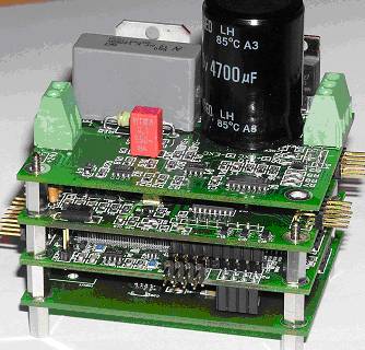
Fig. 2. The panels of the transmitter
Related publication:
Useful link:
Further information: Károly Molnár
|